跳转至内容
  • 版块
  • 最新
  • 标签
  • 热门
折叠
品牌标识

YunTu Forum

YTMicro.com
  1. 主页
  2. Discussion & Question
  3. YTM32B1L系列
  4. SPI DMA example code

SPI DMA example code

已定时 已固定 已锁定 已移动 已解决 YTM32B1L系列
6 帖子 5 发布者 1.8k 浏览
  • 从旧到新
  • 从新到旧
  • 最多赞同
登录后回复
此主题已被删除。只有拥有主题管理权限的用户可以查看。
  • dangho3D 离线
    dangho3D 离线
    dangho3
    写于 最后由 编辑
    #1

    Hello,
    I'm new to this toolchain/MCU. How can I get an example code or setup sequence to configure the SPI using DMA to transmit data?

    Thank you

    1 条回复 最后回复
    1
    • DigaD 离线
      DigaD 离线
      Diga
      写于 最后由 编辑
      #4

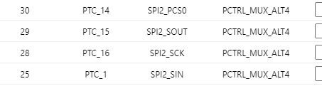
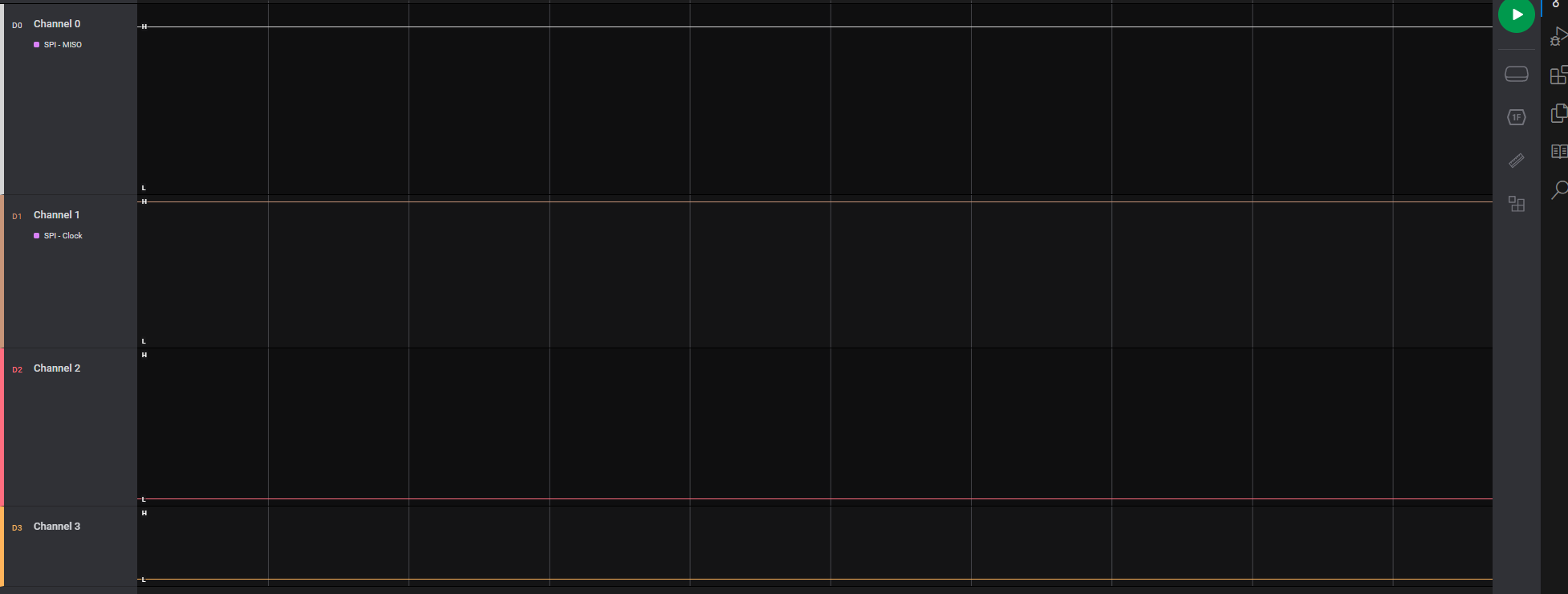
      We download Spi_Master_Dma_Demo code and capture 4 pins shown following.
      13b1b477-1b83-4960-81c5-4ad242e01d28-img_v3_02hd_f1b5693e-39a7-4b60-8024-4e0863ffcf7g.jpg
      img_v3_02hd_2e8ef158-221d-4e05-824f-ccd8192eee6g.jpg
      Maybe you should check pin connection or code if download.

      1 条回复 最后回复
      0
      • qinzhaoQ 离线
        qinzhaoQ 离线
        qinzhao YunTu
        写于 最后由 编辑
        #2

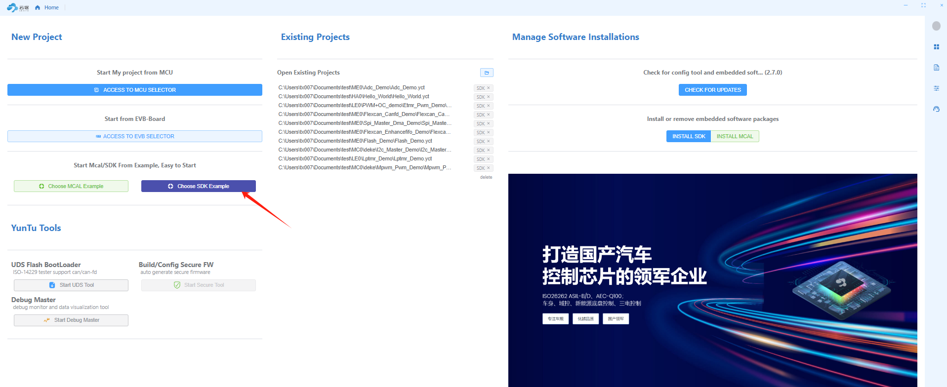
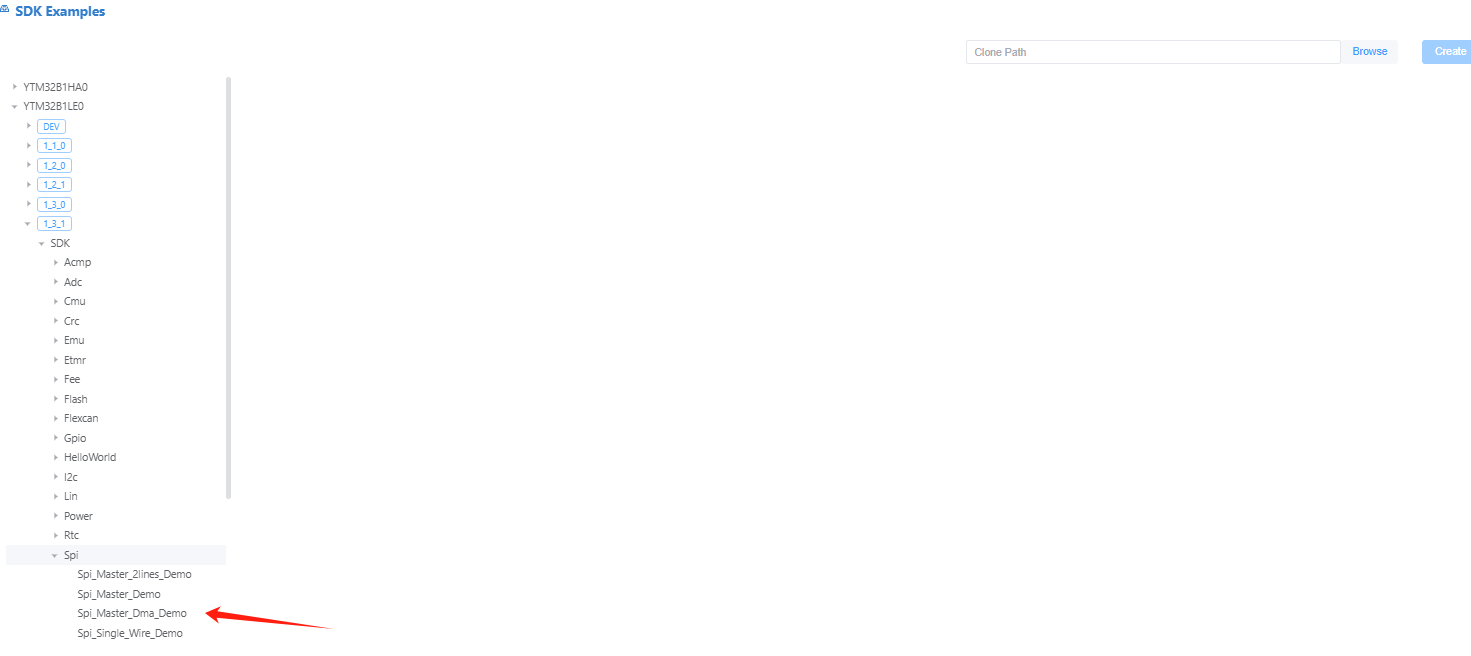
        After installing the SDK in YT Config Tool.
        image.png
        image.png

        1 条回复 最后回复
        0
        • dangho3D 离线
          dangho3D 离线
          dangho3
          写于 最后由 编辑
          #3

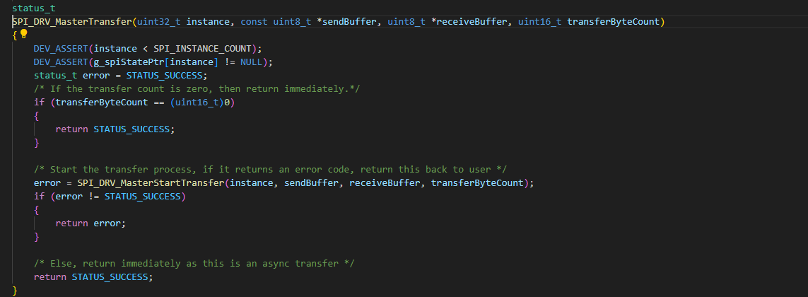
          I have done these steps, but the function "SPI_DRV_MasterTransfer" seem not working cause I have checked the signals on SPI2_SOUT. There isn't any signals

          image.png

          465ef1ec-a4ab-468d-b59d-0e33116a9598-image.png

          1 条回复 最后回复
          0
          • DigaD 离线
            DigaD 离线
            Diga
            写于 最后由 编辑
            #4

            We download Spi_Master_Dma_Demo code and capture 4 pins shown following.
            13b1b477-1b83-4960-81c5-4ad242e01d28-img_v3_02hd_f1b5693e-39a7-4b60-8024-4e0863ffcf7g.jpg
            img_v3_02hd_2e8ef158-221d-4e05-824f-ccd8192eee6g.jpg
            Maybe you should check pin connection or code if download.

            1 条回复 最后回复
            0
            • vonh2V 离线
              vonh2V 离线
              vonh2
              写于 最后由 编辑
              #5

              Hi, thanks for the information, the issue was due to my IAR setup.
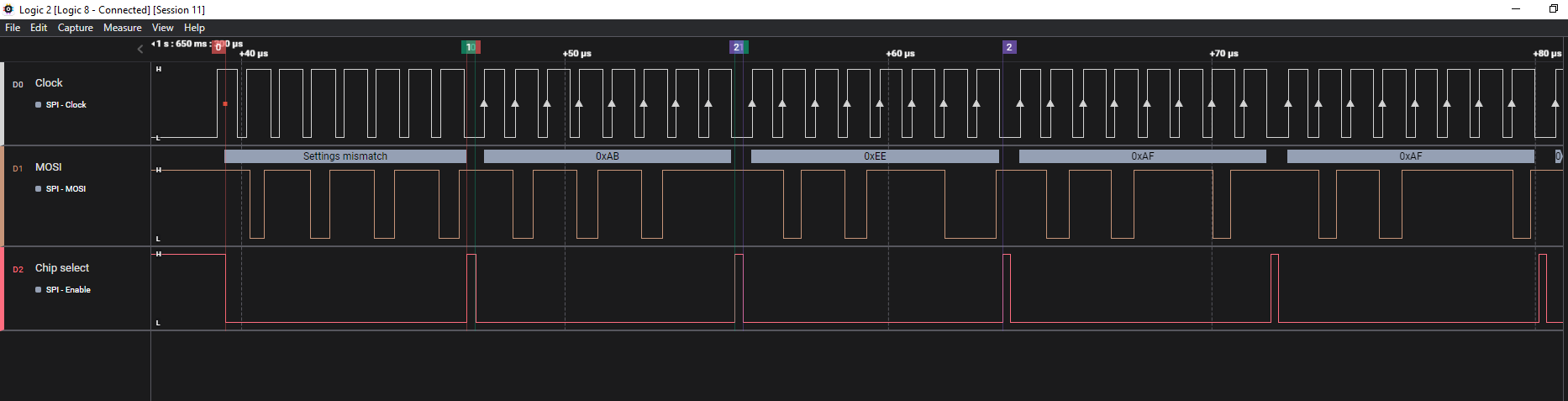
              However, when using the example code. I observed that the PCS timing is not OK (Some time it triggers after the first clock edge) which caused the data corrupted.

              92e62fee-af49-40f9-8ed6-f92bebd23fba-image.png

              1 条回复 最后回复
              0
              • FrankF 离线
                FrankF 离线
                Frank YunTu
                写于 最后由 编辑
                #6

                Hi, If the clock idle polarity is configured as high, during the SPI initialization will provide a low pulse to the clock pin (subsequent low pulses will not occur unless execute de-initilization and Init again). However, since the PCS (Peripheral Chip Select) signal is always activated after the first edge of the clock, it does not affect data transmission.

                1 条回复 最后回复
                0
                • ,FrankieF Frankie 将这个主题转为问答主题
                • ,FrankieF Frankie 将这个主题标记为已解决

              • 云途开发生态介绍

                快速上手云途开发生态

              • 云途论坛规则/Yuntu Forum Rules

                发帖前请查看

              • YT CONFIG TOOL调查问卷

                帮助改进和优化YT CONFIG TOOL,有机会抽取YTM32B1ME0 EVB哦...

              • can
                25
                demo
                22
                lin stack
                13
                uds
                13
                md14
                6
                yt-link
                6
                fbl
                5
                adc模块
                4
                Online Users
                • 登录

                • 登录或注册以进行搜索。
                • 第一个帖子
                  最后一个帖子
                0
                • 版块
                • 最新
                • 标签
                • 热门